-
Courses

Courses
Choosing a course is one of the most important decisions you'll ever make! View our courses and see what our students and lecturers have to say about the courses you are interested in at the links below.
-
University Life
University Life
Each year more than 4,000 choose University of Galway as their University of choice. Find out what life at University of Galway is all about here.
-
About University of Galway

About University of Galway
Since 1845, University of Galway has been sharing the highest quality teaching and research with Ireland and the world. Find out what makes our University so special – from our distinguished history to the latest news and campus developments.
-
Colleges & Schools
Colleges & Schools
University of Galway has earned international recognition as a research-led university with a commitment to top quality teaching across a range of key areas of expertise.
-
Research & Innovation

Research & Innovation
University of Galway’s vibrant research community take on some of the most pressing challenges of our times.
-
Business & Industry

Guiding Breakthrough Research at University of Galway
We explore and facilitate commercial opportunities for the research community at University of Galway, as well as facilitating industry partnership.
-
Alumni & Friends

Alumni & Friends
There are 128,000 University of Galway alumni worldwide. Stay connected to your alumni community! Join our social networks and update your details online.
-
Community Engagement
Community Engagement
At University of Galway, we believe that the best learning takes place when you apply what you learn in a real world context. That's why many of our courses include work placements or community projects.


Galway Astronomical Stokes Polarimeter
Introduction
Members of the Centre for Astronomy have been at the forefront of development in the new area of High Time Resolution Astrophysics (HTRA). Two international workshops were organised in Galway - the latest being in August 2006. A book with refereed chapters ("High Time Resolution Astrophysics", Phelan, D.P., Ryan, O.I., Shearer, A.J., (eds) Springer 2007) was produced from the 2006 workshop. Similarly, a Conference "The Universe on Sub-Second Time Scales" (Royal Observatory Edinburgh, September 2007), supported under FP6 under OPTICON, was organised from the Centre for Astronomy.
As part of an ongoing programme of instrumentation development for HTRA, supported by Science Foundation Ireland, members of CfA are developing the Galway Astronomical Stokes Polarimeter (GASP). The scientific case and design requirements, the basic optical design, and an outline of the calibration of GASP presented below. GASP has been tested on the sky in February 2011 on a calibration run and results will be published in the Proceedings of the 2011 Conference. Further observations will take place in early 2012.
Members
- Prof. Andy Shearer
- Eoin O'Connor
Some Past Members
- Prof. Mike Redfern
- Prof. Chris Dainty
- Dr. Patrick Collins
- Dr. Brendan Sheehan
- Dr. Gillian Kyne
GASP Scientific Case and Design Requirements
The Galway Astronomical Stokes Polarimeter (GASP) is an ultra-high-speed, full Stokes, astronomical imaging polarimeter based upon a Division of Amplitude Polarimeter. It has been developed to resolve extremely rapid (~ms) variations in objects such as optical pulsars and magnetic cataclysmic variables. The polarimeter has no moving parts or modulated components, so the complete Stokes vector can be measured from just one exposure, making it unique to astronomy. The time required for the determination of the full Stokes vector is limited only by detectors and photon fluxes. The polarimeter utilizes a modified Fresnel rhomb, which acts as a highly achromatic quarter wave plate and a beamsplitter.
This polarimeter works by splitting an incoming beam of (unpolarised) light in two components of equal amplitude and using a suitable polarising beam splitter (PBS) in each of the two beams to divide them into two orthogonal linearly polarised beams i(t)1 - i(t)4, see Figure. The ratios of intensities i(t)1 and i(t)2 carry information about Stokes U and Q. An achromatic quarter wave phase retardation (converting circular to linear) is introduced using the GASP prism. The second PBS then examines the ratios of i(t)3 and i(t)4 which carry information about Stokes V. Stokes I is calculated from the sum of i(t)1 + i(t)2 + i(t)3 + i(t)4.
The design of GASP is based upon a DOAP concept by Azzam [2] and then later by Compain & Drevillon [3]. Figure 1 below shows the principle of the design, which is a modification of the Fresnel rhomb - the first broadband quarter wave retarder, described by Fresnel in 1817.
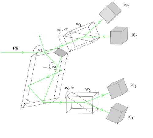
Figure 1: Principle of design of the GASP DOAP where an incoming beam is split in two and then into four by Wollaston (or foster) prisms. Stokes vector is determined by the four intensities i(t)1 - i(t)4.
Introduction
Polarimetry is a useful and underused tool in astrophysics that can facilitate the examination of asymmetries in source regions, magnetic field strengths, scattering centres in nebulae and much more. To basically measure the Stokes vector all one has to do is to measure 6 polarization states (4 linear and 2 circular) and apply to Eq 1. To extract all the polarization information from the vector, apply Eq2 to it and the angles and degrees of polarization can be obtained.
|
I Q U V |
I I.cos(2Θ) I.sin(2Θ) 0 |
| Eq 1: The Stokes vector | Eq 2: Data Reductions for stokes vector |
This vector represents a Stokes vector S(Θ) for an angle of linear polarisation, Θ. I represents the total intensity and is usually set to 1 for any calculations. To produce a circular Stokes vector the above right is multiplied by the Stokes vector for a quarter waveplate.
A motorized PSG (MPSG) and quarter waveplate is used to calibrate GASP. The MPSG is rotated through 180° which describes the linear test and then repeated using the quarter waveplate describing the circular test. This effectively measures at least 6 polarisation states. Data reduction is carried out using the equations above by means of a pseudo inverse method.
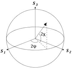
Figure 2: The Pointcare sphere: a 3D representation of polarization
Division of Amplitude Polarimetry (DOAP)
DOAP (see Azzam [2]) can measure the entire stokes vector instantaneously. This is done by splitting the incoming light across a specially coated beamsplitter to divide the light to linear and circular components, then onto a polarising beam splitter. (See Figure 3)
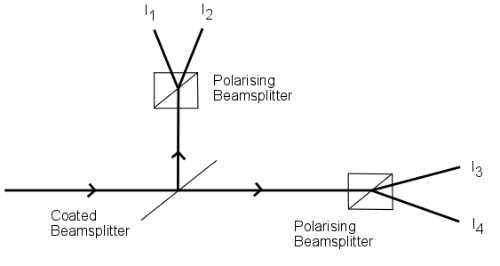
Figure 3: A setup of a Division of amplitude polarimeter [2]
As a result, four beams of different intensities will relate linearly to the input Stokes vector as follows, I = AS where I is a 4x1 intensity vector A is a 4x4 matrix for the system and S is the input vector retrieved from S = A-1I. Only the photon fluxes and detector used will limit the temporal resolution.
Compain & Drevillon [3] describe a DOAP in which a modified Fresnel rhomb, similar to Figure 4, is used. The Galway Astronomical Stokes Polarimeter (GASP) is based upon this design. The prism is designed to act as a highly achromatic quarter wave plate and a beamsplitter. Two retarding beamsplitters (RBS) are used re-image the four beams onto two separate detectors (CCD cameras or APDs) to perform polarimetry.
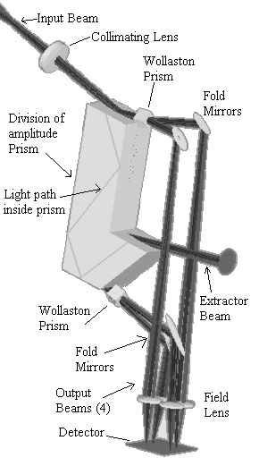
Figure 4: One of the First Versions of the GASP
Optical Design
As this is an imaging polarimeter to use only one camera many optical designs can exist for the GASP. Fig 3 shows a design where two Wollaston are used and each individual beam is picked off with mirrors to a single detector. Obviously one could use 4 individual cameras for each channel generated but then the issue of instantaneous measurement of the Stokes vector would arise. The current design, fig. 4 and 5, have improved the optical quality of its predecessor, simplified the alignment of the instrument, (important for when alignments have to be done in the field) and uses less optics this increasing the throughput and reducing cost.

Figure 5: Optical Layout for current state of the GASP including light path followed through DOAP from telescope focus to detectors
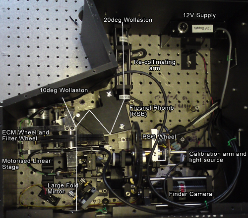
Figure 6: Optical Layout for the GASP used on the WHT (4.2m telescope in La Palma)
GASP Detectors
The detector system is composed of two parts; (1) a fixed back-end that deals with the GPS timing and data storage, and (2) an inter-changeable detector system comprising of APDs and or L3CCD detectors.
Two L3CCD detectors are used for 2-D polarimetric studies; one detector is recording the linear component while the other records the circular component. Both cameras are synchronised to the same 20 MHz signal and thus to GPS. These L3CCD (CCD97 from E2V Technologies) have been optimised to deliver a minimum amount of clock induced charge (CIC) when EM-gain is been used. The rate of CIC generation increases with EM-gain. CIC events may however be distinguished from genuine photon events. The majority of CIC is generated partway along the multiplication register and thus on average experiences less amplification than real photon events. By comparing the distributions for CIC and Photon + CIC, a region is observed separating the genuine photons from CIC events. Here one may threshold the data to remove the CIC and noise components. The level of thresholding must be carefully chosen to maximise the SNR for a particular observation and matched across both L3CCD detectors.
For high resolution (25ns) and faint target acquisition, APD detectors can be used. There are four target APDs with eight sky APDs. They are coupled to the GASP system using optic fibre bundles. Each bundle comprises three fibres. The central fibre is aligned to the optical axis of GASP and is used for target acquisition. On either side of the target fibre lays the sky fibre. Data is recorded using a custom built data logger from PixCellent Imaging, Cambridge, England. This has 15 input channels (8 ST-Fibre ports and 7 TTL BNC ports) and are all sampled at the rate determined by the external clock (40 MHz). All the data logging functions is carried out by an on-board PLD chip. Data is transfer to computer via an Adlink DIO card and stored in binary format to disk. Each photon event is time-tagged to the 25 ns period of the external clock. An in-house Labview interface provides both a real-time data feed as well as a real-time polarimetric analysis for the target.
The field of view for the GASP prism can be limiting for initial finding of targets. To assist to operator a fold mirror, positioned at the focal plane of GASP allows a wide field finder camera to locate the desired target. This finder camera is typically equipped with field sizes ranging from 4-10 arc-min square. For finer pointing the operator then switches to the guider camera located on the extractor arm of the prism. Here the location of the APD fibres within the field are known accurately and allows placement of the target in the correct position for acquisition.
Calibration
The calibration of polarimeters are among the hardest instruments to calibrate in astronomy. The basic calibration method of current polarimeters is to measure the amount of instrumental polarization and subtract it from the data. This means that the polarimeter must be designed to have the analyser as soon as possible in the light path as other elements may depolarize the input. GASP works by purposely polarizing the light before the analysers so a different calibration method is used.
As mentioned above a Motorized Polarization State Generator (MPSG) Generates four linearly independent, optimized [4,5], stokes vectors, which are measured in the lab. The MPSG measures a linear test for 180° in 10° increments. This is repeated after inserting a quarter waveplate after the MPSG. The Stokes vectors for linear and circular polarisation over 180° are calculated (represented by W)and combined with the measured intensity vectors from the lab respectively (I). The system matrix, A (4x4 matrix), is calculated byA=IW-1. No instrumental polarization will exist as this is a total polarimeter and this has been calibrated out. The calibration is verified by measuring polarization and zero polarization standard stars.
Calibration Results Using APD Detectors
The following are calibration plots (compared to theoretical data from Compain [2]) taken using the new APD detector system:
The amplitudes should be noted for each test. There is very little variance between each plot indicating a 25% intensity output between each channel. There is a good match up for the calibration carried out on 2011 Jan 28th. The theoretical data in Figure 7, below, was generated using a Compain [2] matrix which gave an inverse condition number of 0.4864.
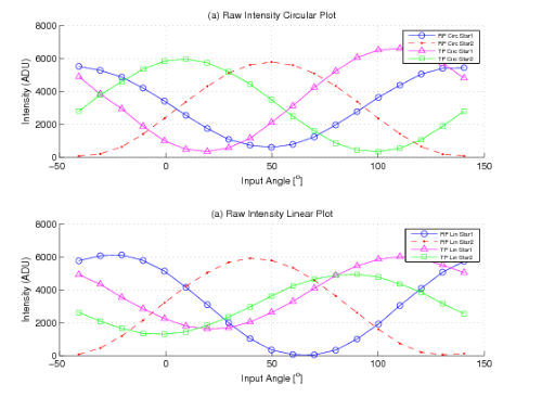
Figure 7: Calibration from 2011 January 28th. GASP Raw Intensity Plots using APD detectors. Note phase difference and amplitudes compared to Compain matrix [2]plots below
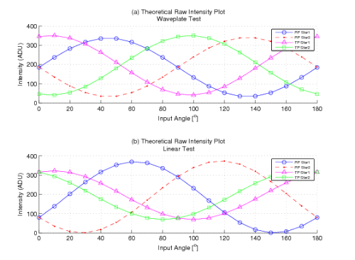
Figure 8: Raw Data Plots using matrix from Compain & Drevillon [2]
Figure 8 (a) and (b) below shows the DOL and DOC for the waveplate calibration, respectively. The expected DOL and DOC will oscillate sinusoidally due to the change in angle for the waveplate test. They will vary at different points as this changing angle becomes linear and circular depending on the orientation compared to the quarter waveplate. Figure 8 (c) and (d) give the DOL and DOC for the linear calibration. 100% DOL and 0% DOC is expected for the linear test.
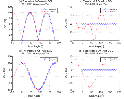
Figure 9: DOL and DOC values for calibration on 2011 January 28th
Figure 9 (a) and (b) show the polarisation and phase angle for the DOL (Degree of Linear Polarisation) and DOC (Degree of Circular Polarisation) using the waveplate. The DOL and DOC will vary sinusoidally between 0 and 100% for the waveplate calibration. This is due to the combination of the linear polariser and quarter waveplate. There are certain combinations of angles for which linear or circular polarisatoin exist. 100% DOC occurs when the linear polariser is at 0° and 0% DOC when at 45°. Figure 9 (c) and (d) show the DOL and DOC for the linear calibration. 100% linear polarisation is expected during this test and 0% DOC. The varying sinusoids suggest systematic errors in the instrument and detectors.
References
- J. Hough, "Polarimetry: Imaging Polarimetry" in Encyclopedia of Astronomy & Astrophysics edited by P. Murdin, IOP Publishing Ltd 2006 - 2000eaa..bookE2901H
- R. M. A. Azzam, Optica Acta, 29 5 685-689 (1982)
- Compain & Drevillon, Applied Optics, 37 25 5938-5944 (1998)
- R.M.A.Azzam et al, J. Opt Soc Am A 5 5 681-689 (1988)
- Compain, et al, Applied Optics, 38 16 3490-3502 (1999)